The idea
Most of my projects live happily in 5 volt Arduino-land of. Occasionally, I need to switch a bit more power. This could be to turn a motor or drive some higher voltage LEDs. In most of my diorama projects I need to combine audio with a combination of RGB NeoPixels and standard LEDs. There are a couple of ways I could tackle this:
Method 1
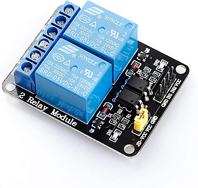
I could use a high voltage relay controlled by the Arduino. There are a ton of plug-and-play modules on the market. They’re easy to use and come in a wide variety of configurations and voltage/amperage ratings. If I were wanting to build something that toggles some significant current on and off, this would be a good direction to explore. Standard relays are, at their core, mechanical switches. They’re easy to understand and the higher voltages/currents are physically separated from the rest of the low voltage electronics. Relays are noisy both electrically and audibly. Any time you make or break an electrical contact, a bit of electronic “noise” is generated and, since these are mechanical, there is an audible click as the relay opens and closes. In many applications, these are non-issues.
Method 2
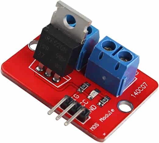
I could use a FET… or MOSFET. To grossly oversimplify, this is an electronic component that allows a small current to control the flow of a larger current. There are also a lot of these modules available for Arduino for the very reason that it’s very common to have a 5 volt Arduino circuit drive motors required higher volts and amps than can be delivered by the Arduino… think robots. MOSFETs are compact, silent, fast, and have the ability to vary the amount of power it’s delivering instead of simply being on or off.
While all of this is brilliant, there are some real considerations. The first thing I worry about is the MOSFET is part of the overall circuit. I’m connecting a 5 volt pin on the Arduino to a leg of the MOSFET that will be controlling a higher voltage. If I get something wrong, bad things happen. The second consideration is heat. Generally speaking, when something is controlling or changing the amount of power moving through a circuit, heat is generated. The filament in a standard lightbulb restricts the amount of current generating heat and visible light. Voltage regulators that step higher voltages down to lower voltages dissipate that excess energy as heat. The greater the voltage difference, the more heat generated… generally. For anything that sits in my house, I want to make sure it’s not a fire waiting to happen so I try to keep voltages a low as needed to get the job done and check to ensure that components are rated well above what I expect them to do.
The project
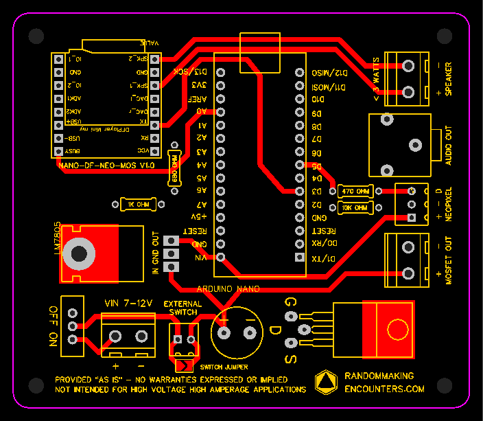
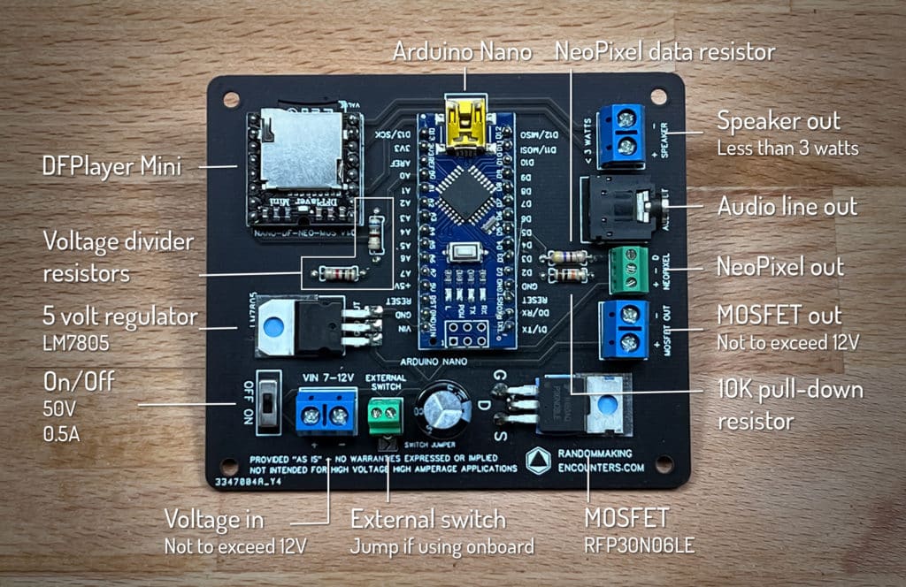
With all of the considerations above, if I had to do it all over again I would probably opt for using an Arduino, a power regulator board, and a MOSFET board and skip most or all that follows. However, I generally never pick the easiest solution so away we go. I decided to build my own board that combines all of the components I generally need to have the following elements:
- An Arduino Nano (or clone)
- A DFPlayer Mini for sound
- An onboard voltage regulator to step up to 12 volts down to 5
- A MOSFET to control up to 12 volts on some external component
- All of the circuitry needed to connect it together as well as allow me to control a string of NeoPixels
The parts
- Arduino Nano – https://amzn.to/3FNIlY6
- DFPlayer Mini – https://amzn.to/3WqVHz8
- Voltage regulator – https://amzn.to/3Ed7FFL
- MOSFET – https://amzn.to/3t0ZqWF
- Micro switch – https://amzn.to/3FN5cTB
- Audio line out – https://amzn.to/3FK1nyf
- Screw terminal, 2 pin, 5mm pitch – https://amzn.to/3TdcP8K
- Screw terminal, 2 pin, 2.54mm pitch – https://amzn.to/3UtmkBL
- Screw terminal, 3 pin, 2.54mm pitch – https://amzn.to/3DwgE36
- Resistors – https://amzn.to/3zLecEU
- Electrolytic capacitor – https://amzn.to/3UKdMqv
- Relay module – https://amzn.to/3Uqe4Cz
- MOSFET module – https://amzn.to/3zLsBky
- Voltage regulator module – https://amzn.to/3Wybb4w
Build notes
Check out this post for information on how and where I fabricated the circuit board. I am not a PCB-electronics-formally-trained-wizard so take all information with a heaping helping of salt. The traces are 1mm and, according to this calculator, should be able to handle a couple of amps. Most of the components are rated well above my goal of controlling a handful of 12 volt LEDs but the real wildcard is the number of LEDs on the strand. The number of amps an LED strand draws is dependent on the number and type of LEDs. If we use this strand as an example, one meter contains 60 LEDs and draws 1.2 amps. This EXCEEDS the maximum amperage rating for the slide switch but reducing the number to 20 LEDs would bring things down to around 0.4 amps. If I need to power something that draws above 0.5 amps, I would probably not use the slide switch and just jump that connection or wire in a switch with a higher amp rating.
This is a very purpose-built board that includes a pull-down resistor connected to the pin that controls the MOSFET, resistors that form a voltage divider to protect the DFPlayer input pin, and a resistor on the pin that controls the NeoPixel data line. There isn’t any consideration given to accommodate PWM to control the MOSFET. This article explains the additional components needed to “condition” the output from the Arduino. That may be for another day and another project.
Code examples
					// toggle power to mosfet

void setup() {
  // pin 4 controls the mosfet
  pinMode(4, OUTPUT);

}

void loop() {
  // writing pin 4 to high turns the mosfet on
  // the mosfet voltage is the same as the voltage to the board
  digitalWrite(4, HIGH);
  delay(1000);
  // writing pin 4 to low turns the mosfet off
  digitalWrite(4, LOW);
  delay(1000);
}
					// blink mosfets and set neopixel colors

// must include the adafruit neopixel library
#include <Adafruit_NeoPixel.h>

// define pins
// digital pin 4 controls the mosfet
int mosfetpin = 4;
// digital pin 5 controls the neopixels
int pixelpin = 5;
// number of pixels in the strand
int numpixels = 4;

// set up neopixel strip
Adafruit_NeoPixel strip(numpixels, pixelpin, NEO_GRB + NEO_KHZ800);

void setup() {
  // pin 4 controls the mosfet
  pinMode(mosfetpin, OUTPUT);
  // start neopixels
  strip.begin();
  // clear neopixels
  strip.clear();
}

void loop() {
// illuminate each pixel in the strand one at a time
  for (int i = 0; i < numpixels; i++) {
    strip.setPixelColor(i, strip.Color(100, 0, 100));
    strip.show();
    delay(100);
  }
  // writing pin 4 to high turns the mosfet on
  // the mosfet voltage is the same as the voltage to the board
  digitalWrite(mosfetpin, HIGH);
  delay(1000);
  // writing pin 4 to low turns the mosfet off
  digitalWrite(mosfetpin, LOW);
  // clear neopixel values
  strip.clear();
  strip.show();
  // pause before looping
  delay(1000);
}
Resources
Using MOSFETs and Arduino – http://adam-meyer.com/arduino/rfp30n06le-arduino
Adafruit NeoPixel Uberguide – https://learn.adafruit.com/adafruit-neopixel-uberguide
DFPlayer Mini documentation – https://wiki.dfrobot.com/DFPlayer_Mini_SKU_DFR0299